3D Scanning System using Structured Light
Visgraf - 2003
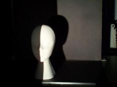
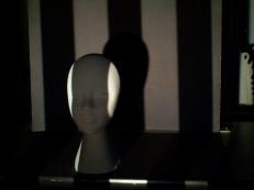
Image capture
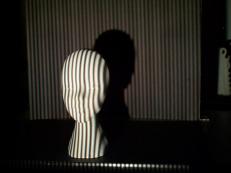
The main scan step is to capture images of
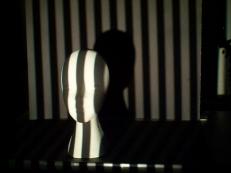
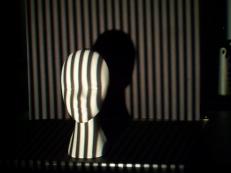
an object illuminated by a projected pattern consisting of vertical stripes
of different widths. This structured light method allows us to generate
a set of images as shown below.
|
|

|
|
|
|
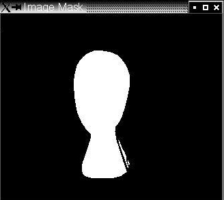
Our scan script automatically projects normal and inverse images of the pattern on the object and then the images are captured by our system and stored with specific names in a folder containing all the object's data (for example, pictures and calibration files). The script also projects and captures two additional images: one totally white and another completely black. These images are used to identify shadow areas, to determine a threshold for stripe identification and to create a "mask" image for background removal.

|
|
Stripe determination
To find the coordinates of
the points at the stripe boundaries in all resolutions we subtract the
normal and the negative images of the object and determine with subpixel
accuracy where the sign changes in pixels intensity occurs. The zero-crossings
represent the boundary points.
Then, we need to identify
every stripe with an unique code. Since we projected stripes with different
widths using the Graycode pattern, all we need to do is to look at each pixel
and give it a code of 1 if it is white or 0 if it is black. Therefore we
obtain a N-bit Graycode (where N is the resolution level, for example, 8).
Each stripe code is converted to a decimal number representing the x-coordinate
in the projector frame of reference. All this procedure is done by our active triangulation
module. After that, the program saves a list with the valid boundary points
index (those not removed by the mask) and their subpixel coordinate.