3D Scanning System using Structured Light
Visgraf - 2003
Calibration
The intrinsic parameters are the focal length (on both directions x and y), the coordinates of the center of projection and the distortion factor. The extrinsic parametrs are the rotation matrix and translation vector (R and T, respectively). With these parameters we can find the relative position between the camera and the projector in 3D space.
To do this, we need a plane in space that can be used as reference for both the camera and the projector. This plane can be identified if we use a checker board as pattern (a common procedure among calibration methods) and examine it with a camera. Then we need to reproduce this same pattern with the projector.
We developed a script that
first calibrates the camera, by taking a picture of the checker board pattern.
Then, we remove this pattern, leaving only a white background on the plane
and then we calibrate the projector, reprojecting a check borad image on
the same plane and capturing another picture of it.
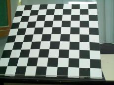
The check board pattern as seen by the camera |
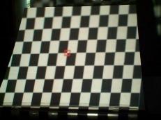
Projected check board pattern |
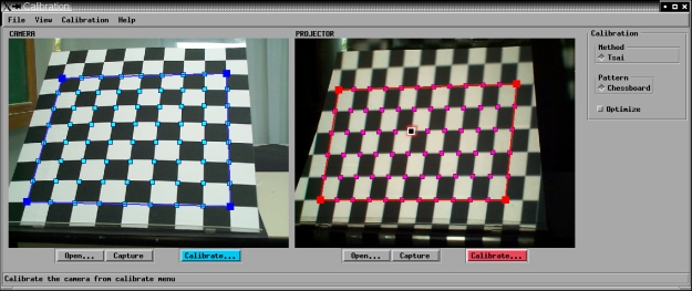
Using our calibration software
we identify all the corners of the black and white squares of the pattern, first for
the camera image, then for the projector. Our system runs a least squares algorithm (as the Tsai calibration method)
retrieving the intrinsic parameters for both. With this information, the software returns the camera and
projector positions in space, expressed by their rotation and translation
parameters. Calibration parameters are saved for the active triangulation
procedure.
|
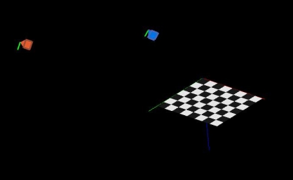
The 3D output of the scene is shown below.
|